Setting up a safe and reliable van power system is a vital part of any DIY van conversion. It’s essential to get it right and understand what you’re doing.
When we installed our first vanlife solar electrical system back in 2016, we were complete newbies to solar power, batteries, and electrical wiring. And doing it ourselves felt hugely intimidating.
Since installing that first system, we’ve gained a ton of real-world experience wiring and living with off-grid solar setups. And we’re here to share that knowledge to make your van build easier.
In this post, we go over everything you need to know to install your own campervan electrical system. We cover basic fundamentals, designing your system, selecting components, and how to wire a camper van. We provide tools, calculators, resources, recommendations, and van wiring diagrams to help you along the way.
Once you’re done reading, you’ll have the knowledge you need to hit the road, get off-grid, and power all the electrical devices you need for van life.
This post is adapted from our ebook Vanlife Solar Basics.
Are you tired of jumping from website to website trying to wrap your head around your van’s electrical system? Our comprehensive guide covers everything from fundamentals to components to sizing to installation, all in one easy-to-follow package.
Vanlife Electrical System Configurations
Let’s start with a quick overview of common configurations for a camper van electrical system, as well as some recommended components.
The rest of the post digs into the details of what all of this stuff does, how it fits together, and how to design and install your own system.
200W Basic Solar System
This system is a good bare minimum for basic power on the road. It will power the basics, but if you’re running a camper van fridge and a vent fan you may need to rely on your DC-DC charger to keep your batteries topped off. This system is also easily expandable as your needs grow.
|
LFP Battery
|
Solar Panels
|
Charge Controller
|
Inverter
|
DC-DC Charger
|
|
1 (100Ah total)
|
2 (200W total)
|
1
|
1
|
1
|
|
High performing and affordable LFP battery with low temp protection. The best bang-for-your-buck battery option out there. |
Top quality solar panels at an affordable price. Enter discount code Gnomad8 for 8% off at Renogy.com |
Efficiently charge your batteries from solar. Enter discount code Gnomad8 for 8% off at Renogy.com |
Power your AC devices with grid-quality electricity. Enter discount code Gnomad8 for 8% off at Renogy.com |
Charge your batteries while you're driving. Enter discount code Gnomad8 for 8% off at Renogy.com |
|
|
High performing and affordable LFP battery with low temp protection. The best bang-for-your-buck battery option out there.
Top quality solar panels at an affordable price.
Enter discount code Gnomad8 for 8% off at Renogy.com
Efficiently charge your batteries from solar.
Enter discount code Gnomad8 for 8% off at Renogy.com
Power your AC devices with grid-quality electricity.
Enter discount code Gnomad8 for 8% off at Renogy.com
Charge your batteries while you're driving.
Enter discount code Gnomad8 for 8% off at Renogy.com
400W General Purpose Electrical System
This system is probably the most common size for a vanlife electrical system. It will accommodate most general use cases, including running a refrigerator and vent fan.
|
LFP Batteries
|
Solar Panels
|
Charge Controller
|
Inverter
|
DC-DC Charger
|
|
2 (200Ah total)
|
4 (400W total)
|
1
|
1
|
1
|
|
High performing and affordable LFP battery with low temp protection. The best bang-for-your-buck battery option out there. |
Top quality solar panels at an affordable price. Enter discount code Gnomad8 for 8% off at Renogy.com |
Efficiently charge your batteries from solar. Enter discount code Gnomad8 for 8% off at Renogy.com |
Power your AC devices with grid-quality electricity. Enter discount code Gnomad8 for 8% off at Renogy.com |
Charge your batteries while you're driving. Enter discount code Gnomad8 for 8% off at Renogy.com |
|
|
High performing and affordable LFP battery with low temp protection. The best bang-for-your-buck battery option out there.
Top quality solar panels at an affordable price.
Enter discount code Gnomad8 for 8% off at Renogy.com
Efficiently charge your batteries from solar.
Enter discount code Gnomad8 for 8% off at Renogy.com
Power your AC devices with grid-quality electricity.
Enter discount code Gnomad8 for 8% off at Renogy.com
Charge your batteries while you're driving.
Enter discount code Gnomad8 for 8% off at Renogy.com
600W-800W High Power System
This system is great for vanlifers who want to maximize their use of power on the road. You should be able to do just about anything you want short of powering an air conditioner or electric heater.
|
LFP Batteries
|
Solar Panels
|
Charge Controller
|
Inverter
|
DC-DC Charger
|
|
3 (300Ah total)
-OR- 4 (400Ah total) |
6 (600W total)
-OR- 8 (800W total) |
1
|
1
|
1
|
|
High performing and affordable LFP battery with low temp protection. The best bang-for-your-buck battery option out there. |
Top quality solar panels at an affordable price. Enter discount code Gnomad8 for 8% off at Renogy.com |
Efficiently charge your batteries from solar. Enter discount code Gnomad8 for 8% off at Renogy.com |
Power your AC devices and charge your batteries from shore power. Enter discount code Gnomad8 for 8% off at Renogy.com |
Charge your batteries while you're driving. Enter discount code Gnomad8 for 8% off at Renogy.com |
|
|
-OR-
4 (400Ah total)
High performing and affordable LFP battery with low temp protection. The best bang-for-your-buck battery option out there.
-OR-
8 (800W total)
Top quality solar panels at an affordable price.
Enter discount code Gnomad8 for 8% off at Renogy.com
Efficiently charge your batteries from solar.
Enter discount code Gnomad8 for 8% off at Renogy.com
Power your AC devices and charge your batteries from shore power.
Enter discount code Gnomad8 for 8% off at Renogy.com
Charge your batteries while you're driving.
Enter discount code Gnomad8 for 8% off at Renogy.com
Fuses, Wiring & Connectors
The major components are only half the story – you’ll also need fuses and wiring to connect everything (we dive into all of this later in the post). Properly sizing your wiring and fuses is vital for safety, so be sure to follow our sizing guidelines.
High End Van Electrical Systems
If you’re planning on building out a high end system with nothing but the best-of-the-best components (and have the budget for this), then we recommend going one of two routes, depending on how much wiring you want to do.
Option 1: DIY system using Victron components
Victron components are the gold standard. If this is the type of system you’re building, we highly recommend purchasing a customized Victron Power Kit from Unaka Gear Co. These kits come bundled with all your main components, and you can add on the Wiring Kit for everything you need for your electrical install.
|
Main Components
|
Wiring & Connectors
|
LFP Battery
|
Solar Panels
|
|
Quantity:
1
|
Quantity:
1
|
Quantity:
1
|
Quantity:
6-8 (600W-800W total)
|
|
Description: Victron solar components bundled together in a convenient package. Enter discount code GNOMADHOME for 5% off at Unakagearco.com |
Description: Everything you need to install Unaka Gear Co's Victron Power Kit. Enter discount code GNOMADHOME for 5% off at Unakagearco.com |
Description: Bulletproof LFP battery that interfaces with other Victron components. Enter discount code GNOMADHOME for 5% off at Unakagearco.com |
Description: Top quality solar panels at an affordable price. Enter discount code GnomadHome for 10% off at Renogy.com |
|
|
|
Victron solar components bundled together in a convenient package.
Enter discount code GNOMADHOME for 5% off at Unakagearco.com
Everything you need to install Unaka Gear Co's Victron Power Kit.
Enter discount code GNOMADHOME for 5% off at Unakagearco.com
Bulletproof LFP battery that interfaces with other Victron components.
Enter discount code GNOMADHOME for 5% off at Unakagearco.com
Top quality solar panels at an affordable price.
Enter discount code GnomadHome for 10% off at Renogy.com
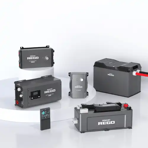
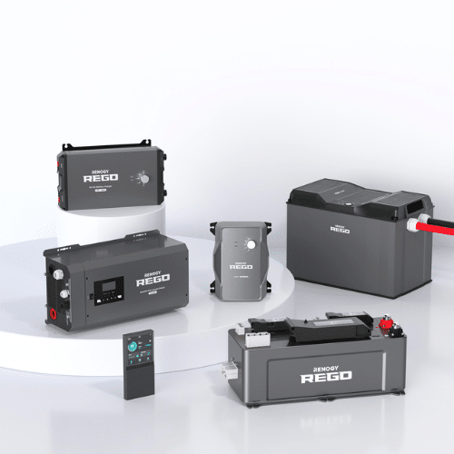
Option 2: Renogy REGO plug-and-play system
Renogy’s REGO system is a high capacity solar electrical kit (400Ah battery and a 3000W inverter) that snaps together using beefy Anderson connectors. No cutting, crimping, or attaching wires. If you want a big system but are feeling intimidated by actually wiring things together, these REGO kits are as simple as it gets.
|
Main Components & Connectors
|
Solar Panels
|
|
1
|
6-8 (600W-800W total)
|
|
Full plug-and-play system that's dead simple to install. Enter discount code Gnomad8 for 8% off at Renogy.com |
Top quality solar panels at an affordable price. Enter discount code Gnomad8 for 8% off at Renogy.com |
|
|
Full plug-and-play system that's dead simple to install.
Enter discount code Gnomad8 for 8% off at Renogy.com
Top quality solar panels at an affordable price.
Enter discount code Gnomad8 for 8% off at Renogy.com
How a Campervan Electrical System Works
Let’s start by breaking everything down from a bird’s eye view.
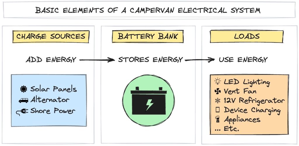
At the most basic level, your van’s electrical system captures and stores energy to use on the road.
Every off-grid camper electrical system includes
- charge sources, which add energy
- batteries, which store energy
- electrical loads, which use energy
Let’s go over these in broad terms (we’ll get into the nitty gritty details later).
Charge Sources
Charge sources add energy to your battery bank. Charge sources for van battery systems include
- solar panels
- your van’s alternator, and
- shore power (i.e., plugging in at a campground or friend’s house)
Solar should be your primary charge souce, but having a backup can be a lifesaver when traveling through heavily forested areas or dealing with extended periods without adequate sunlight. We recommend installing a DC-DC charger for alternator charging.
Battery Bank
The battery bank stores energy and is the heart of any camper van electrical system. Your battery bank may be one battery or multiple batteries wired together.
The batteries for your camper electrical system are separate from your vehicle’s starter battery. This separate battery bank is referred to as an auxiliary battery, house battery, or leisure battery.
Electrical Loads
Electrical loads discharge energy from your batteries. Typical loads in a van build include
- LED lighting
- ventilation fans
- 12V refrigerators
- water pumps
- kitchen appliances
- internet devices (hotspot, cell booster, Starlink, etc.)
- device charging (phones, computers, tablets, etc.)
Basic Components of a Van Life Electrical Setup
Now that we understand the big picture of van electrical systems, let’s go over the essential components to make charging, energy storage, and discharging happen.
Solar Panels
Solar panels absorb light from the sun, convert it to electricity, and send it to the charge controller. The electricity created by your solar panels is in the form of Direct Current (DC). Most vanlifers mount solar panels on the roof of their vans so that they’re constantly absorbing sunlight (well, at least when the sun’s out).
Read More: Best Solar Panels for Campervan Power Systems
Charge Controller
The charge controller regulates the flow of electricity from the solar panels and uses it to charge your batteries. Different types of batteries require different charge profiles, and your charge controller ensures that your batteries are being charged and maintained properly.
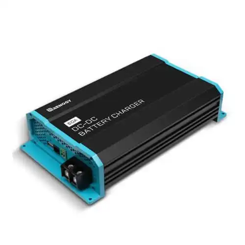
DC-DC Charger (or battery isolator)
A DC-DC battery charger (also called a battery-to-battery charger) connects to your van’s starter battery and uses the power generated by your alternator to charge your leisure batteries while you’re driving. This is a vital backup power source since it lets you charge your battery bank just by turning on your engine.
Battery isolators can also fulfill this function, but DC-DC chargers offer significant advantages, and using an isolator is not an option for modern vans equipped with smart alternators.
Read More: Best DC-DC Chargers for Van Life
Batteries
Batteries store DC electricity for later use. Although DC electricity can exist at various voltages, campervan electrical systems are typically 12V DC (we’ll dig into what all this means further down).
The DC current in your batteries can be used directly to power DC appliances such as 12V refrigerators, ventilation fans, LED lighting, and anything that plugs into a cigarette lighter plug. To power AC appliances, you first need to use a power inverter to convert the DC current from your batteries to AC.
Power Inverter
An inverter converts direct current (DC) to 120V alternating current (AC), which is the type of current that comes out of the wall in a stationary dwelling. You need an inverter in your camper van electrical system to power anything that plugs into a typical wall outlet, including blenders, coffee grinders, Instant Pots, laptops, and televisions.
Read More: Best 12V Power Inverters for Vanlife
Wiring
Wiring connects all of these components together. Your wiring should be sized based on the maximum current that will run through it, so you’ll have multiple wire sizes in your van build – from thinner wiring for your LED lights to thick battery cable for your batteries and inverter (more on properly sizing wires later on).
Fuses & Breakers
Fuses are essential safety devices that prevent catastrophes in your van life electrical system. If something goes wrong and there’s suddenly too much electrical current, fuses will “blow,” cutting off the electricity before it overloads your wiring. Fuses are vital for preventing overheating, fires, and other dangerous issues. (Breakers are similar to fuses, except where fuses blow and need to be replaced, breakers “trip” and can be reset).
Typical camper van power systems include larger fuses for main components (like your charge controller, batteries, and inverter) and “fuse blocks,” which are a collection of multiple smaller fuses in a single enclosure. Fuse blocks distribute power to your loads and give you a single spot to check for blown fuses.
Bus Bars
Bus bars are strips of metal that serve as common connection points for your van electrical wiring. The biggest use for these is organizing all the things that connect to your battery bank. Rather than attaching a jumble of wires to your batteries, you connect your batteries to positive and negative bus bars and wire everything else to those.
Your DC fuse block will also include a negative bus bar for connecting all the negative wires for your smaller components.
LED Lighting
LED lighting is typically wired throughout your van and connected to your DC fuse block. There are a few different types of LED lighting, including puck lights, strip lights, and Christmas lights. We highly recommend wiring your lights to a dimmer switch for chill evening vibes.
Receptacles
Receptacles are anything that you “plug in” to. DC receptacles are wired to your DC fuse block and include 12V cigarette lighter outlets, USB outlets, and others. AC receptacles are standard wall outlets and get power from your inverter.
A Word on Portable Power Stations for Van Life
A DIY electrical installation isn’t the only way to get electricity in your van. If you’d prefer a more plug-and-play solution, consider a portable power station instead.
Portable power stations are all-in-one devices that include the components we just listed above in a self-contained box (well, except the solar panels and lighting). They are essentially rechargeable lithium battery packs with a built-in solar charge controller, power inverter, DC and AC receptacles, and inputs for solar, DC, and AC charging. If you want a basic camper van electrical system without a lot of hassle, power stations are about as easy as it gets.
Not all power stations are built for the rigors of full time road life. A basic power station can provide your electrical needs for shorter trips, but if your goal is to create an electric system for long term van living you need something beefier. Our favorite power station right now is the Bluetti AC200P, which gets you a 2000Wh (167Ah) battery, 2000W inverter, and the ability to drop right into a 12V DC electrical system. If you need more battery capacity, the AC200Max allows you to add on more batteries.
On the other hand, wiring your own DIY camper van electrical system gives you the flexibility to design it exactly as you see fit. And if up front cost is your primary concern, you can save a bunch of money starting small and adding on later.
Read More:
Important Concepts for Campervan Electrical Systems
This section covers essential electrical concepts and terminology that will help you understand what’s happening in your van power system.
Volts, Amps, and Watts
Three fundamental electrical terms you need to know are Volts, Amps, and Watts.
You’ll encounter these terms a lot when you’re picking components and designing your campervan electrical system, and it’s vital to understand how they work together.
To help visualize the relationship between Amps, Volts, and Watts, let’s use the analogy of water flowing down a mountain stream.
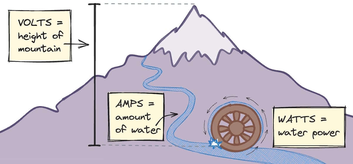
Amps (A) measure electrical current. This is like the amount of water flowing down the mountain.
Volts (V) measure the electrical force that pushes the current. This is like the height of the mountain.
Watts (W) represent electrical power, which is determined by Amps x Volts. This is like the water power generated by the stream, which we can use to turn a water wheel (power appliances). More Amps or more Volts increases the wattage (power) coming out of a circuit.
THE Fundamental Equation For Your Van Electrical System
There is one simple equation that you need to know in order to understand the electrical setup in your van build.
Amps = Watts / Volts
Many electrical components are sized in Watts, but when designing your system, you need to know how many Amps everything will draw to size your wires and fuses properly. To figure that out, divide Watts by your system voltage (usually 12V).
Do you have a 12V fan that draws 36W on high? 36W / 12V = 3A, so the fan draws 3A of current.
You can also reverse this to calculate Watts:
Watts = Amps x Volts
If you need to calculate the amount of Watts and you know the amperage, just multiply Amps by your system voltage. So in the previous example, 3A x 12V = 36W.
Note: This equation is technically derived from Ohm’s Law, which is a bit more complicated, but you don’t need to know all the details here. As long as you understand this basic equation, you’ll be fine.
Basic Circuitry: What You Need to Know
Understanding how circuits function helps a lot when designing, wiring, and troubleshooting your camper van electrical system.
Here’s a diagram of a simple DC circuit.
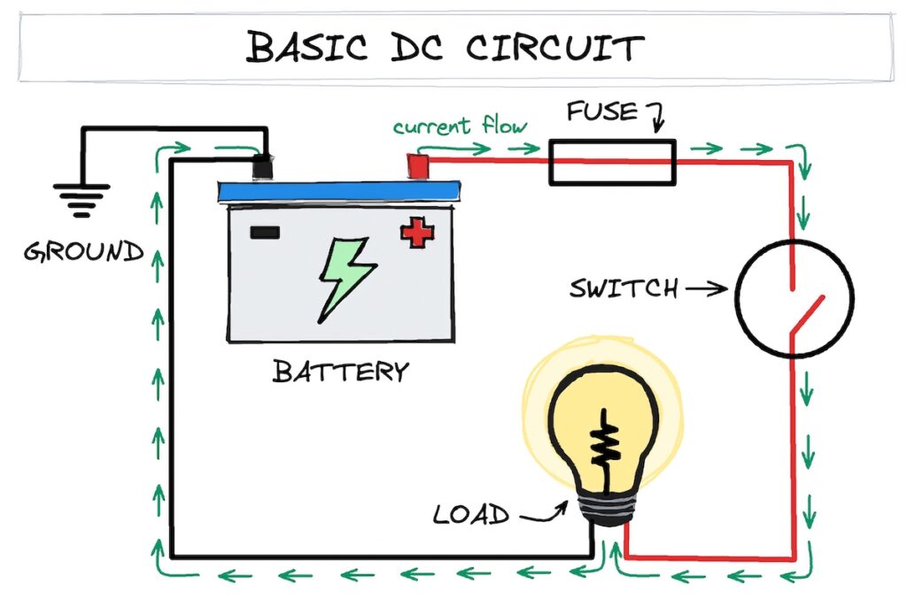
There are a few important points to note here.
- Electrical current wants to flow from higher voltage to lower voltage – think of it like water flowing downhill. The positive battery terminal has a higher voltage than the negative battery terminal, so current always flows from positive to negative (“downhill” from higher voltage to lower voltage). Along the way, it passes through your circuits and powers your devices. This is why a circuit must always form a loop between the positive and negative battery terminals.
- A switch allows you to break the current flow. This is useful for turning things on and off (like lights) or cutting the electricity when you’re working on your van’s electrical system.
- A fuse is an intentional weak point in a circuit. It’s there for safety. If too much current flows through a fuse, it will “blow” and break the circuit. This prevents your wiring from being overloaded, and is vital for preventing catastrophes like fires, explosions, or opening portals to other universes.
- Grounding your vanlife electrical system is a connection from the battery negative to your vehicle’s chassis. This is an important safety feature that can prevent you from getting seriously injured if there’s a short circuit.
Sizing Your Camper Van Electrical System
When designing an off-grid electrical system for your van, the first step is to decide how big of a system you’re going to install. There are two approaches to this.
- The first is to calculate how much power you use (or expect to use) and size your campervan electrical system based on your usage.
- The second is to size your electrical system based on your budget and plan your power usage around your system size.
We’ll go over both of these approaches in this section.
Calculating Solar System Size in 4 Easy Steps
When sizing your van’s solar system, you first need to figure out what exactly you’re trying to power. That then determines how much battery power you need and how much solar power it will take to recharge your batteries.
If you’ve never lived in a van before, you won’t know much about your real-world electrical usage on the road. But going through these steps is still a great exercise because it forces you to think through the details before making expensive decisions about your campervan electrical system.
Step 1: Calculate your power consumption in Watt-hours (Wh)
This step sounds intimidating, but it’s pretty easy.
First, list out all of the devices/appliances/components you plan on using, along with the amount of Watts each of them draws. It helps to do this in a spreadsheet.
Note: Not sure where to find this info? It should be easily available in the instruction manual, spec sheet, or on the internet (just search “name/model of component” + specifications, or “name/model of component” + manual).
Next, calculate how many hours you plan on using each component per day. Multiply the Watts by the hours, and you have Watt-hours (Wh).
Watts x hours = Wh
So, if your LED lighting uses 3W and you have them on for 5 hours each day, their power consumption is 15Wh per day (3W x 5 hours = 15Wh).
Step 2: Determine how much battery capacity you need (Ah)
For this example, let’s pretend all your electrical components use 2400Wh each day.
Battery capacity is measured in Amp-hours (Ah), so to figure out how many batteries you need, convert the 2400Wh of power consumption into Ah by dividing it by the system voltage (12V).
2400Wh / 12V = 200Ah
Based on this calculation, you would need 200Ah of battery capacity.
But wait – we’re not done!
When we’re talking battery capacity, we’re talking about usable battery capacity. And to figure out usable battery capacity, we need to factor in the type of battery that you have.
- LFP batteries can be 100% discharged without damage. That means a 100Ah LFP battery has a usable capacity of 100Ah. So, we don’t need to make any changes to our capacity calculation to factor in an LFP battery (unless you want to build in some cushion).
- AGM batteries can be regularly discharged down to 50% without damage. So, we’ll factor in an AGM battery in our capacity calculation by dividing the initial result by 0.5.
Let’s redo that calculation, but this time factor in the different battery types.
- LFP battery: 2400Wh / 12V = 200Ah
- AGM battery: 2400Wh / 12V = 200Ah / 0.5 = 400Ah
For 2400Wh of power consumption, you’ll need a 200Ah LFP battery or a 400Ah AGM battery. Both of these batteries have a usable capacity of 200Ah.
Step 3: Size you inverter based on your battery bank size and AC power usage
We’ll use a rule of thumb here to keep things simple. For every 100Ah of usable battery capacity, you can install up to 1000W of inverter power.
So in our example with a 200Ah LFP battery bank, you can install up to a 2000W inverter.
Then, double check your AC power consumption from step 1 and make sure your inverter wattage is higher than the total wattage of AC loads you plan to power at the same time.
If you’re not powering many AC devices you might be able to get a smaller inverter. But if you need more inverter power than your battery can handle you’ll also need to size up your battery bank to accommodate the additional current draw of your AC power system.
Want to actually calculate this? Divide the inverter wattage by 0.9 to account for inefficiency, then divide by 12V. Here’s the equation: inverter wattage / 0.9 / 12V = Amp draw of inverter. Make sure your battery bank’s max continuous output current is above this number.
Example: 1000W / 0.9 = 1,111W / 12V = 93A
Step 4: Calculate how much solar power you need to fully charge your batteries each day (in Watts)
You want to size your solar panel system so that it can fully charge your batteries each day.
The general rule of thumb here is to install a minimum of 200W of solar for every 100Ah of usable battery capacity. This translates to 200W of solar for every 100Ah of LFP batteries (or every 200Ah of AGM batteries).This is a minimum number. Solar panels are cheap enough that it’s always a good idea to add more solar to account for different conditions.
Note: If you want to get more specific, you can divide your battery capacity (1200Wh) by the average amount of peak sun hours that will be hitting your solar panels. This ranges from 4-6 hours per day in the continental US, so using a number in that range makes sense (the rule of thumb above assumes 6 hours – 1200Wh / 6 hours = 200W). In the real world you’ll get more sun in the South and in summer, and less in the North and in winter. Adjust your peak sun estimate based on your expected travel patterns.
Budget-Based System Sizing (or, how much solar can you afford?)
Sizing your system appropriately can be challenging, especially if you’ve never lived in a van before. There’s just a lot you won’t know about your real-world electricity usage in your van and a lot you won’t be able to foresee before you hit the road.
Another method is to take a budget-based approach to your campervan electrical system and add capacity as needed.
If you have a bare-bones budget, you don’t need a huge, expensive solar power system. But if you can afford it, having a large solar setup will make your life easier and means fewer compromises in your electrical usage.
Note: It’s still a good idea to go through the sizing steps above to see where you may need to adjust your electrical usage (or to ensure you don’t buy way more solar than you need).
It’s important to think about future upgrades when you’re selecting components for a low budget system.
For example, if you buy a 20A charge controller because it’s cheaper, you might have to buy a whole new charge controller before you can add more solar panels. If you start off with a 40A charge controller, then you’ll have more room to upgrade.
Below are the main components we recommend for different budget levels.
Note: The systems below are examples, and you can swap components as needed. For example, you can use budget LFP batteries for the larger systems, or upgraded batteries for the smaller systems, etc.
Lower Budget
This small van electrical system gets you started on the right foot, with good lithium batteries and 200 Watts of solar. This setup is completely expandable, so you can add more house batteries and solar later if you need to.
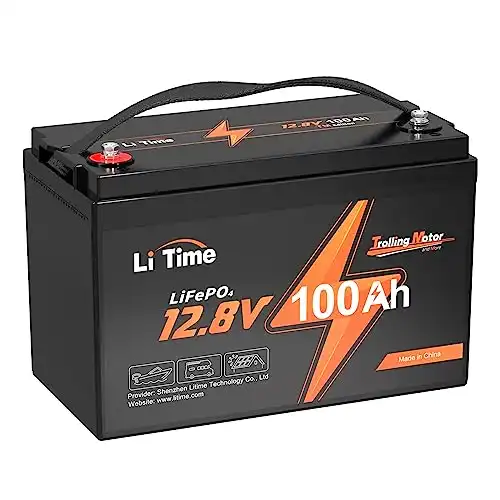
- 100Ah budget LFP battery
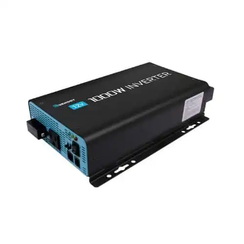
- 1000W pure sine wave inverter
- 40A DC-DC battery charger
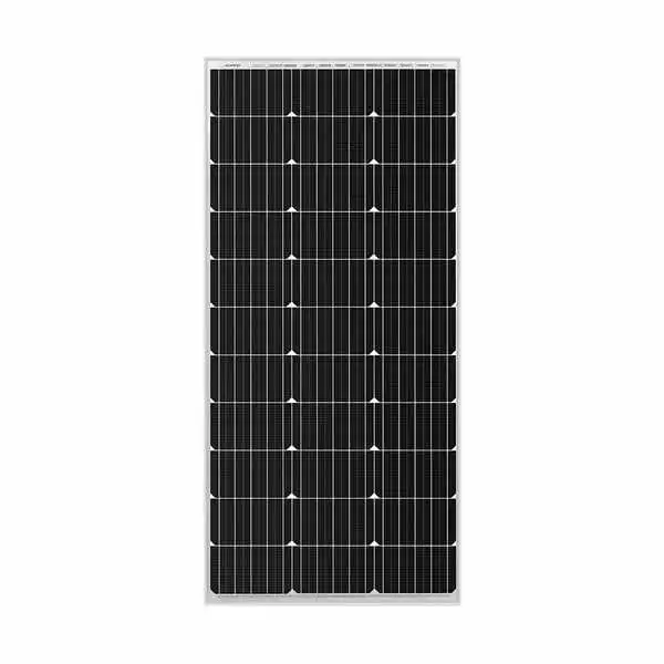
- (2) 100W solar panels
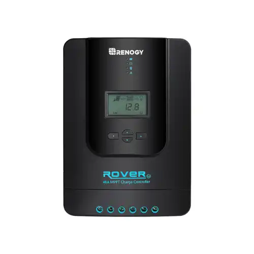
- 40A MPPT charge controller
Upgrade pathway: Add two more 100W panels and another 100Ah LFP battery.
Don’t have the budget for solar? Start off with the battery, inverter, and DC-DC charger from this list (so you can charge while driving). This will cover very basic needs, and you can add on the solar panels and charge controller later.
Midrange Budget
With a midrange budget, spend that extra money adding more solar panels and battery power. A 400W system like this will take care of most power needs like running fans, a fridge, lighting, appliances, and device charging.
- (2) 100Ah budget LFP batteries
- 2000W pure sine wave inverter
- 40A DC-DC battery charger
- (4) 100W solar panels
- 40A MPPT charge controller
Higher Budget
If you have a higher budget, you can upgrade to midrange+ lithium batteries and add/or add more solar and battery capacity as needed. An inverter/charger adds the ability to carge via shore power.
- 2 x 100Ah midrange LFP batteries (or more)
- 2000W pure sine wave inverter/charger
- 60A DC-DC battery charger
- 4 x 100W solar panels (or more)
- 60A MPPT charge controller
Note: The Renogy 400W Premium solar panel kit bundles the solar panels and charge controller with mounting brackets, wiring, and MC4 inline solar panel fuses. The Renogy Complete Kit throws in Renogy’s Smart LFP Lithium batteries and a 2000W pure sine wave inverter.
Renogy Discount Code: Enter code GNOMADHOME at checkout for 10% off at Renogy.com.
Highest Budget
This electrical system both sizes up to accommodate robust electrical needs, and upgrades your setup to premium components.
- 4 x 100Ah premium LFP batteries
- 2000W pure sine wave inverter/charger
- 60A DC-DC battery charger
- 800W solar –> (8) 100W panels OR (4) 200W panels
- 100A MPPT charge controller
If you’re looking at this type of system with 400Ah of battery capacity, consider the Renogy REGO power system. This plug-and-play kit includes all of the above components in an easy-to-install package that snaps together using high-amperage Anderson connectors. No need to buy or crimp battery cable, which makes things way easier (and safer). Just plug everything in and you’re good to go.
Full plug-and-play system that's dead simple to install. No wiring, no confusion. Includes 400Ah LFP battery, MPPT charge controller, DC-DC charger, 3000W inverter-charger, and system combiner.
Enter coupon code Gnomad8 for 8% off at Renogy.com
Important Note: Don’t underestimate the cost of wiring and fuses! Proper (and high quality) fuses, wiring, and connectors really add up, and this is an area you don’t want to skimp on. Expect to spend at least $300 for these items, even for smaller budget systems.
Selecting Your Van’s Main Electrical Components
Now that you’ve sized your camper van electrical system, let’s talk about how to select the specific components in your van build.
Should You Get a Solar Panel Kit?
The first choice you need to make is whether you want to go with a solar kit or select your components individually.
Solar panel kits bundle most of your main components, and are often cheaper than buying everything individually.
If you’re a beginner to solar power and the idea of selecting every part of your system feels intimidating, buying a solar panel kit can be a great way to cut down on decisions and stress. You lose the ability to customize your components, but that’s usually not a huge issue unless you have very specific needs.
Even though solar kits simplify things quite a bit, most kits don’t come with everything – so you may still need to pick up the right batteries, an inverter, a DC-DC charger, and some other connecting pieces. Also, not all kits are created equal – we recommend avoiding “budget” kits with PWM charge controllers, for example.
We’re big fans of Renogy Premium Solar Kits for their ease of installation right out of the box. You still need batteries and an inverter, but they come with everything else for a good bundle price. And you’ll have the flexibility to choose batteries based on your budget. They’re also available in a variety of sizes, so there’s a kit for you no matter your electrical needs.
If you want to simplify things even further, Renogy also makes a complete solar kit that includes batteries and an inverter. Or buy into their plug-and-play REGO system, which features robust major components that easily attach together without messing with wiring.
Read More: Best RV Solar Panel Kits That Are Actually Legit
If a solar panel kit isn’t for you, read on for more info on choosing your camper van electrical system components individually.
Choosing Solar Panels
Solar panels come in three form factors, and there are also a few types of solar cells to know about. First, the form factors.
Rigid solar panels are more affordable, more durable, and have a longer lifespan than other types (20-25 years). However, they are more difficult to install, especially on vehicles with curved roofs. They also stick off the top of your rig, which can make stealth camping in cities more difficult.
Flexible solar panels are easier to install on curved or irregular roofs, and they’re far less noticeable. However, they are more expensive, less durable, and have a shorter lifespan (3-5 years). If stealth is more important to you than your budget, flexible panels may be a good option.
Portable solar panels won’t be your primary source of solar power. But if you want an extra panel to set up at camp or a mobile charge source for a solar generator, they can be useful.
There are also three main types of solar cells you’ll encounter when designing your electrical system:
- Monocrystalline solar panels are what we recommend for most people. They’re more efficient than other types (which means they produce more power from the same surface area), and they’re inexpensive. You can get monocrystalline panels in both rigid and flexible form factors.
- Polycrystalline solar panels are not as efficient, but they’re slightly cheaper. However, the small amount you’ll save isn’t worth the lower efficiency.
- Thin film amorphous solar panels (such as CIGS panels) are highly bendable flexible panels that are more durable than flexible mono panels and produce more power in low light conditions. However, they’re about twice the cost of flexible mono panels. These are an interesting option, but out of reach of most budgets.
With monocrystalline panels, you’ll also have a choice in the number of bus bars (BB) included – the more bus bars, the greater the efficiency, and the less the panels are affected by partial shading. The best solar panels for campervans and RVs are the newer 9BB panels.
Read More: The Best Solar Panels for Van Conversion Power Systems
Bottom Line: Go with rigid monocrystalline 9BB solar panels for the best combination of cost, efficiency, and durability. Unless you have a huge budget and prioritize stealth camping – then you could consider flexible panels.
Choosing a Solar Charge Controller
A solar charge controller takes the voltage produced by your solar panels and regulates it down to properly charge and maintain your van’s leisure batteries. How it does this depends on the type of charge controller.
There are two types of solar charge controllers, and each uses a different mechanism for reducing the voltage from your solar panels.
PWM (pulse width modulation) charge controllers reduce the solar voltage by rapidly switching on and off. While this works for charging your batteries, it loses a ton of solar power in the process – up to 30% of your solar output.
MPPT (maximum power point tracking) charge controllers convert the excess solar voltage into current, and funnel that into your house batteries. This is much more energy efficient, charges your house faster, and works better with higher voltage solar arrays (like you’ll have on your van).
PWM controllers are super cheap, but you’ll be losing a ton of solar efficiency by using one. Meaning you’ll either have less power or you’ll need more solar panels to make up the difference, which eats up your cost savings from buying the cheaper charge controller. If you’re living in a vehicle full time, we recommend just going with MPPT from the get go.
Once you’ve decided on the type of charge controller, you need to make sure it’s properly sized.
- Size your charge controller based on the recommended charge rate of your battery bank. If your battery’s charge rate is 40A, get a 40A charge controller.
- Make sure your charge controller’s max input voltage is higher than the total voltage output of your solar panels.
Bottom Line: Get an MPPT charge controller that’s properly sized for the output of your solar array and your battery bank’s charge rate.
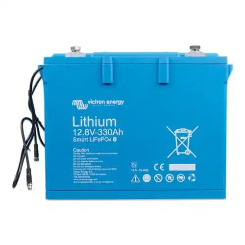
Choosing Batteries
There are several different types of batteries, but the main ones to know about for vanlife electrical are LFP (lithium iron phosphate or LiFePO4) and AGM (absorbed glass matt, a type of lead-acid battery).
LFP batteries are lighter, charge faster, and can be 100% discharged without damage. Because they can be fully discharged, sizing everything is much simpler and you don’t have to worry as much about the state of your batteries day-to-day. LFP batteries are more expensive upfront, but they’re cheaper over time because they last a lot longer.
AGM batteries are much heavier, and you need to be careful not to over-discharge them. Because they can’t be regularly discharged beyond 50%, you need to constantly monitor them and be careful with your electrical usage when they’re getting low. AGM batteries are cheaper upfront, but they’re more expensive over time because they need to be replaced more often.
It used to be that lithium batteries cost so much more than AGM batteries that they didn’t make sense without a huge budget. But these days the cost has come down enough to make LFP batteries the clear choice for all but the lowest budgets.
Bottom Line: Go with lithium batteries – they’re lighter, simpler to deal with, and perform better. AGM batteries only make sense for super barebones budgets – you’ll have more headaches and the upfront cost savings vs LFP quickly diminishes over time.
Choosing an Inverter
There are two types of inverters: pure sine wave (PSW) and modified sine wave (MSW). Modified sine wave inverters are much cheaper and can work just fine, but we recommend going with a pure sine wave inverter for your van’s AC power system. Here’s why.
- Pure sine wave inverters output a cleaner electrical signal that’s closer to what you’ll get from the electric grid.
- This means that it’s safer to power sensitive electronics like computers, and loads like motors, microwaves, and induction cooktops will run much more efficiently.
- The “dirtier” signal of a modified sine wave inverter can shorten the life of these AC devices.
- There are also some appliances that will not run on a modified sine wave.
If you’re on a very tight budget, you can pick up a cheap MSW inverter and it will meet most basic needs. But a PSW inverter is the way to go for most people.
Do you plan to include a shore power hookup in your rig? If so, you can go with an inverter/charger, which integrates an inverter, battery charger, and transfer switch in one unit. Inverter/chargers can simplify adding shore power to your rig, and the built in transfer switch comes in handy if you use a lot of AC power. But these units can also be bulky and expensive. Getting just an inverter and adding a standalone battery charger can also work well, and is often cheaper. But that’s another component to wire into your system, which adds complexity.
Read More: The Best 12V Power Inverters for Van Life
Bottom Line: Get a pure sine wave inverter. If you plan to add a shore power plug to your camper’s electrical system, consider going with an inverter/charger.
Choosing a DC-DC Charger
Choosing a DC-DC charger (also called a battery-to-battery chargers or B2B charger) is mainly a matter of considering your battery charge rate.
This ties back to your battery chemistry and battery bank size. DC-DC chargers come in different charging amperages (20A, 40A, 60A, etc.). You need to make sure you get the appropriate size for your battery’s charge rate. You can undersize this, but don’t oversize it.
Here’s the general rule of thumb for battery charge rates:
Most lithium batteries can be charged at 50% of capacity, meaning a 100Ah lithium battery can be charged at a maximum of 50A. AGM/lead acid batteries can be charged at 20% of capacity, meaning a 100Ah AGM battery can be charged at a maximum of 20A.
(Note: Always check the specs to get the max charge current for your specific battery).
If you have an older rig, you can use a battery isolator or split charge relay for alternator charging, but these are not an option for newer vans with smart alternators or for lithium batteries.
Read More: Best DC-DC Chargers and Battery Isolators for Vanlife
Bottom Line: Get a DC-DC charger that’s sized for your battery bank’s charge rate.
All About Wiring and Fuses (Super Important)
Don’t overlook wiring and fuses when designing your campervan electrical system.
It’s easy to focus on the main components, but using the right wiring and fuses is vitally important for the safety and performance of your system. The cost can add up as well, so make sure to include this in your budget.
Important Note: Wiring and fuses are not things you should skimp on. There are tons of low-quality products on Amazon that may not perform as advertised, and you’re putting yourself at risk using them.
Choosing the Right Fuses for Your Campervan
A fuse is an intentional weak point in a circuit. If the current in the circuit ever gets dangerously high, the fuse will “blow,” breaking the circuit and saving you from major problems.
Choosing the right fuses is very important for safety. You need to size your fuses appropriately for the wiring that they’re protecting, but you also need the right type of fuse for what you’re fusing.
- For your larger components (inverter, charge controller, DC-DC charger), we recommend
- ANL fuses inside inline fuse holders
- OR MRBF fuses inside an MRBF fuse block
- OR MEGA fuses inside a Victron Lynx Distributor (combo bus bars and fuse block)
- For solar panels wired in parallel we recommend using inline MC4 fuses at the point where each solar panel enters the parallel wiring connector.
- For your small DC electrical loads (lights, outlets, fan, fridge, etc.), we recommend wiring everything into a blade fuse block and picking up a set of blade fuses.
- For AC receptacles (outlets) wired to your inverter we recommend using a small AC breaker box and standard breakers.
Alternatively, you can use an RV AC/DC distribution panel for both your AC and DC loads.
Read More: When Do You Need to Fuse Solar Panels? (and how to do it)
Fusing Your Batteries
Properly fusing your battery bank is so important for safety that it deserves its own section. Best practice is to place your battery fuse as close as possible to the positive terminal. You can accomplish this by using a terminal-mounted fuse block, or by placing a proper fuse within 7” of the main positive terminal (per ABYC standards).
With that in mind, let’s go over the fuses that are acceptable for fusing your leisure batteries.
- MRBF fuses. You can mount these fuses directly to the positive battery terminal, so they do the best job of fusing your batteries as close as possible to the power source. MRBF fuses are acceptable for both LFP and AGM batteries, however you should use these on each individual battery of an LFP battery bank (do not use a single MRBF fuse for multiple LFP batteries).
- Class T fuses. The high interrupt rating of these fuses makes them suitable for all types of batteries, and even for fusing two LFP batteries in parallel. However, Class T fuses can be pricey and difficult to find, and we prefer the convenience of terminal-mounted MRBF fuses.
- ANL fuses (single AGM batteries ONLY). ANL fuses are only suitable for single AGM batteries. Their interrupt rating is not high enough to protect LFP batteries or multiple AGM batteries in parallel.
Other types of fuses are not acceptable for fusing batteries, period.
Bottom Line: we recommend using MRBF fuses mounted directly to the positive terminals of each battery you’re using. Alternatively, you can fuse your battery bank with a Class T fuse. Do not use anything other than MRBF or Class T fuses for LFP batteries.
Choosing Wiring for Your Campervan Electrical System
Choosing proper wiring is very important for the safety and performance of your electrical system. You’ll have three general types of wiring in your van build:
- Primary wire (12 – 16 AWG) is what you’ll use to to wire all your loads to your DC fuse block and inverter/breaker box.
- Battery cable (4/0 – 8 AWG) is what you’ll use to connect your larger components (batteries, inverter, charge controller, DC-DC charger)
- Solar wire (10 AWG) is UV-protected wire that you’ll use to connect your solar panels to your charge controller. You must use solar-specific wiring because regular exposure to sunlight will quickly deteriorate other types of wire.
Here are some tips for selecting your van wiring:
- ONLY buy stranded wire. Do not buy solid core wiring, because it will come loose with all the vibrations of a moving vehicle.
- ONLY buy copper wire (solid copper or tinned copper). Do not buy aluminum wiring, because it is not as effective at conducting electricity. You’ll need much thicker wiring for the same load, and it’s easy to undersize it and cause issues.
- For your DC loads, buy stranded duplex wire (two wires inside a single sheath) to make installation easier. Copper speaker wire also works well for this.
- For your AC loads, buy stranded triplex wire (three wires inside a single sheath), since AC electrical has three wires (hot, ground, and neutral).
- For your battery cable, copper welding wire is usually a good bet. You can buy this by the foot, or in bundles of red and black.
- Marine-grade wiring and battery cable is top quality, but expensive.
The vinyl or rubber coating on the outside of wiring is called insulation, and it comes in different colors. But you’ll want to stick with the standard colors for your wiring because this makes it much easier to understand what’s going on with your electrical system.
Standard DC wire colors:
- Red = positive
- Black = negative
Standard AC wire colors:
- Black = hot
- White = neutral
- Green = ground
Note: In the United States, wire size is measured in American Wire Gauge (or AWG). AWG may be different than wire gauges used in other countries.
Calculating Wiring and Fuse Sizes for Your Van Build
Choosing proper wiring and fuse sizes is a crucial step in any van life electrical install.
- As a general rule, choose fuses that are above the max current of your circuit load
- Check the manuals for larger components like your solar charge controller, inverter, batteries, solar panels, and fridge for manufacturer-recommended fuse sizes
- Choose wiring that can handle at least as many Amps as your fuse
Wire sizes should be based on the max current going through the wire before the fuse blows and the length of the wire run. You want to use wires thick enough to safely handle the maximum electrical current of your circuits without experiencing too much voltage drop (the voltage lost as electricity flows through your wiring).
We’re looking at this on a circuit-by-circuit basis, so you’ll need to repeat these steps for each circuit.
Step 1: Calculate current draw for the circuit (in Amps)
Your lights, appliances, and other electronics should have their max current listed in their technical specifications.
For DC appliances, this should be listed in Amps (max amperage). If your component specs list this in Watts, divide that number by the system voltage (so divide by 12 for a 12V DC power system).
Special note for inverters: Inverters add a tad more complexity because you need to take into account the efficiency rating. A 2000W inverter that’s 90% efficient draws more than 2000W from your battery.
To account for this inefficiency, we’ll divide the inverter wattage by 0.90. For example, a 2000W inverter can actually draw 2,222W (2000W / 0.90 = 2,222W). Once we have the power draw in Watts, we can divide that by the system voltage (12V) to get the max current.
Step 2: Multiply the current draw by 1.25 to get the max current for fuse sizing
We want to fuse each circuit above the maximum amount of current that the appliances on it will draw. The standard rule of thumb here is to go 25% higher to add some cushion and reduce the chance of the fuse blowing during normal conditions.
Multiplying the current draw by 1.25 gives us a max current that’s 25% higher than the current draw. Once you get your number, round up to the nearest available fuse size.
Step 3: Calculate the total length of the wire run for each circuit
First, you’ll need to measure the distance the wiring will travel (distance between start/end point, i.e., fuse box → outlet. Or battery → inverter, etc.).
Then double it.
What?! Double it?! Yup.
When calculating wire sizing for DC systems, the wire length refers to the total length of both the positive wires and the negative wires.
So if you’re wiring an outlet that will be 5 feet from your fuse box, your wire length is actually 10 feet – 5 for the positive wire and another 5 for the negative wire to complete the circuit.
Step 4: Refer to a calculator or chart to determine minimum wire size
Use this wire size calculator to determine the wire gauge you should use for your van build. Simply enter the system voltage, the max current, and the total wire length. The calculator will spit out the recommended wire gauge for you.
You can also take a look at this handy wire-size infographic for a quick visual reference.
Note: Fuses exist to protect your wiring from overheating and causing a fire. You can use wire sizes that are smaller or larger than recommended – as long as you use a fuse that’s sized for the wiring.
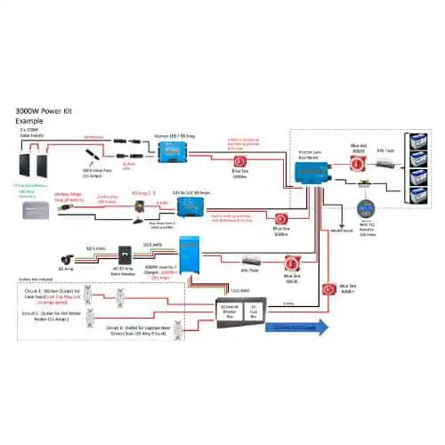
Electrical System Design & DIY Camper Van Wiring Diagrams
In this section, we’ve put together some basic wiring diagrams for different sized electrical systems. You can use these as a starting point, but we highly recommend drawing out your own wiring diagram so you know exactly how everything is supposed to connect. This really helps you think through your electrical system and get it straight in your head, including things like wire and fuse sizes that will be specific to your setup.
Here’s an example wiring diagram for a typical 400W system:
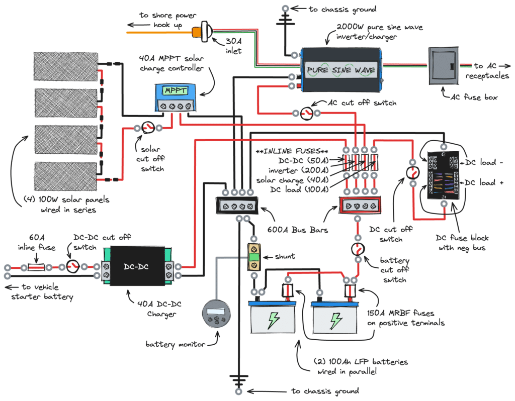
We’ll have more diagrams coming soon.
Installing Your Camper Van Electrical System
Now for the fun part – actually getting electricity in your van!
This can also be the most intimidating step, especially if you’ve never done electrical work before. But fear not! We’ll go over the basics you need to know.
Tools You’ll Need
Let’s start off with general tools and power tools you should have around.
- Power drill and impact driver
- Ratcheting screwdriver
- Needle nose pliers (can also cut wires)
- Ratchet & socket set. You’ll need this for all kinds of things, from fuse holders to battery terminals to random bolts.
- Insulated ratchet handles. You really don’t want to use a metal ratchet handle when you’re working with your batteries. If your hand slips and you drop the ratchet, you can easily short out your battery if it touches both terminals (ask us how we know).
- MC4 assembly tool. This makes disconnecting MC4 connectors easier (you can do this with your fingers, but it takes some practice).
- Electrical tape
You’ll also want to have a multimeter, which is a device for taking electrical measurements like voltage and current. A basic multimeter is just fine.
For keeping your wiring organized, it’s a good idea to pick up:
- Zip ties/cable ties. For bundling wiring together and general organization.
- Cable clips. For attaching wiring to walls, floor, etc.
- Wire looms. For protecting wires and battery cable in areas where the insulation might rub against metal (underneath the van, going through holes, etc)
- Grommets (optional). For taking the edge off of holes in metal that wiring passes through.
Cutting, Stripping, and Crimping Wires & Battery Cable
How do all your wires connect to each other and your components? With crimp connectors!
Crimping thinner gauge wires (22AWG – 10AWG)
For crimping thinner gauge wires (22AWG – 10AWG) you’ll need to use three kinds of crimp connectors in your van build.
- Ring terminals connect all the wires for your DC loads to the your DC fuse block and negative bus.
- 1/4″ female quick disconnects connect all the wires for your DC loads to the backs of your DC receptacles.
- Butt splice connectors allow you to crimp two or more wires together (such as when you’re connecting to the wires coming off your vent fan). They also allow you to “pigtail” wires together in a chain, which saves on wiring when you’re connecting lights in series.
All of these crimp connectors are color-coded based on the wire gauge they’re designed for.
- Red = 18-22 AWG
- Blue = 14-16 AWG
- Yellow = 10-12 AWG
We recommend getting quality heat shrink connectors, which have heat shrink built in for protecting your electrical connections.
What tools do you need to crimp wires? A basic electrician’s multitool will have you cutting, stripping, and crimping wires in no time. Although these tools are cheap and versatile, they’re not as precise at getting a solid crimp.
If you want to get a little more serious, we highly recommend picking up a ratcheting crimp tool for no-nonsense crimps that you know are strong. Another great tool upgrade is this wire stripper. These two tools will seriously up your game, and make intense wiring jobs much easier and faster.
Read More:
For crimping thicker battery cable (8 AWG – 4/0 AWG) you’ll use lug connectors, which are essentially larger ring terminals. Crimping battery cable is a little more difficult than thinner wiring and requires specialized crimping tools.
The most basic type of crimper for battery cable is a hammer-style crimp tool. This type of crimper is inexpensive, portable, and fairly easy to use, but it’s also easier to crimp improperly.
There are also mechanical crimp tools and hydraulic crimp tools. Hydraulic crimp tools should give you the best results, but they’re bulky and expensive – which means it might not make sense if you’re only using it for one build (we used a hammer-style crimp tool for our first build, but we’ve since upgraded to a mechanical crimper, which works great).
You’ll need a few general tools for working with battery cable:
- cable cutters
- heat gun
- Stripper (dedicated strippers are best, but you can use a box cutter in a pinch)
You’ll also need heat shrink and cable lugs sized for the cable you’re crimping. We recommend going with tinned copper lugs, for their high electrical conductivity and corrosion resistance. Some lugs come with heat shrink.
Check out this video for a tutorial on crimping your own battery cable (the video shows crimping battery terminals, but the instructions apply to basic ring lugs also).
If you don’t feel like messing with crimping your own battery cable, you can buy pre-made battery cables in various sizes with ring terminals already attached. The downside is that you’ll lose some flexibility in the placement of your electrical components, and the cost can add up quickly. Another option is to order custom-length battery cables.
Electrical Install and the Van Build Process
There are so many different stages of a van build. At what point do you actually install all of your electrical wiring?
You can get started installing your electrical system as soon as you have a place to mount your components. However, we generally recommend waiting until you’ve insulated your van, installed your flooring, and built any furniture that will hold electrical components. It’s best to install wiring above your insulation for easier access. Wait to put up your walls and ceiling until after you’ve installed your wiring, in case any wiring runs behind it.
Note: Solar panels should be mounted before you insulate your ceiling in case you need to reinforce anything from the inside.
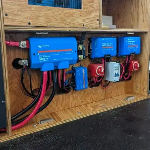
Plan the Layout of Your Components
Before diving into your electrical install, it helps to have an idea of exactly where everything will go. Once you’ve decided on the location of your electrical hub, dry-fit your components and mark their positioning.
Some things to think about when you’re planning your layout:
- Place your batteries as close as possible to your main chassis ground connection.
- Place your positive and negative bus bars as close as possible to your batteries, and the negative bus bar as close as possible to your ground connection.
- Plan it so your inverter is as close as possible to your bus bars and also to the ground connection.
- Map out where smaller things like inline fuses, switches, and wire runs will go. You want to keep things contained but not too cramped.
- Make sure you can easily access your electrical components in case you need to fix something down the road.
- Think about weight distribution in your van. You don’t want all your heavy components like electrical, water tanks, etc, grouped on one side. Try to keep things even.
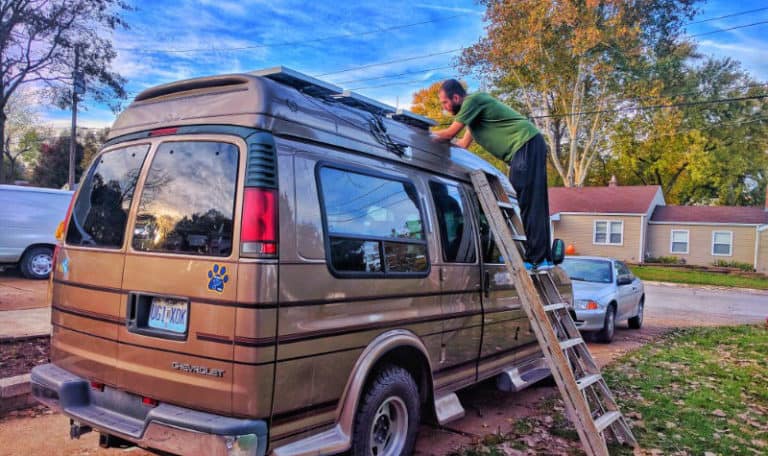
Install Solar Panels on Your Van
Exactly how you mount your solar panels depends on your rig, your roof, the type of solar panels you’re using, and whether you have a roof rack.
If you have a flat metal roof, you can mount your solar straight on. Most rigid solar panels come with z-brackets and sheet metal screws for mounting, but we highly recommend using stainless steel bolts instead, attached with large washers and lock nuts on the inside. This helps distribute the load across a greater surface area and makes things more secure.
If you have a curved fiberglass roof, you’ll need some kind of spacer to even things out, which can get complicated.
If you’re using flexible solar panels, you can mount them without actually drilling into your roof. It’s important to leave some airflow space underneath the panels to prevent them from overheating. Industrial strength velcro will adhere the panels to your roof while leaving a small gap. Another option is to first mount your solar panels on a sheet of cloroplast for airflow before adhering them to your roof.
If you have a roof rack, you can just mount your solar panels directly to it. This minimizes the need for drilling holes, allows plenty of airflow, and helps make the solar panels less obvious for stealth camping.
Important: Whatever mounting method you choose, it’s vital to seal any hole you drill in your roof.
Read More: Mounting Solar Panels on a Fiberglass Van Roof
Wire the Solar Panels Together
Important: DO NOT connect your solar panels to the charge controller until the batteries are connected. It’s also a good idea to cover your panels with a blanket while wiring them so they’re not producing electricity.
You can wire your panels together in either series or parallel, but you’ll need to purchase additional wiring connectors and solar fuses for parallel wiring.
- For series wiring, the panels connect in a chain, with the negative wire of one panel connecting to the positive wire of the next, etc.
- For parallel wiring, all the positive wires go together, and all the negative wires go together.
Which wiring scheme should you go with? We recommend series wiring in most cases.
The argument against series wiring is that since the solar panels are wired in a string, shading on any of the panels drastically cuts the output of all the panels. However, the real world impact of this is minimal, and is far outweighed by the positives of wiring in series.
The big advantage of series wiring is that your solar panel voltage adds together (amperage stays the same). So four solar panels with an open circuit voltage of 24V wired in series will produce up to 96V, which then gets regulated down by your MPPT charge controller.
This means that it will be much easier to hit the voltage required to charge your batteries in low light conditions (like early morning, evening, and cloudy days), which ultimately means your batteries will charge faster and longer.
Read More: Should You Wire Your Solar Panels In Series Or Parallel?
Bottom Line: Series wiring is the way to go for your solar panels. It’s simpler, charges your batteries faster, and doesn’t require fuses or additional connectors.
Bring the Wiring Inside the Van
After you mount your solar panels, you need to get the wiring inside your van. This means drilling a hole in your van to feed the wires through.
To prevent water from penetrating, make sure to cover up the hole with a solar entry gland. To attach the entry gland to the roof, use 3M VHB tape and seal it up with Dicor lap sealant.
Where exactly do you feed the wiring through? It depends on the location of your main electrical components. We recommend planning it so you can feed the solar wires down into one of the main van ribs, which offer a nice open space to run a bunch of wiring.
Mount Your Main Components
At this point you’ll have planned the layout of your primary electrical components, dry fit everything, and marked the positioning. Now it’s time to actually mount your components, including
- charge controller
- inverter
- fuse blocks
- bus bars
- cut off switches
- inline fuses
Make sure to think about where the wiring will travel, especially the bigger battery cables since these are more difficult to bend.
Wire Up Your Batteries
Place your batteries in their spot, and make sure they’re secure. You can do this by placing them in a box or enclosure, or by holding them down via a ratchet strap or battery hold down.
If you have more than one 12V battery, wiring them in parallel is the way to go for a campervan electrical system. To do this, connect the positive terminals together with thick wire, then connect the negative terminals.
Make sure your wires are all of equal length so that current will flow evenly between the two batteries. Size the wire to accommodate the max current flow of your entire system.
Example: Your entire system has a max current of 300A, and you plan to connect your batteries with 12” wires. Per the wire size calculator you’ll need to use 2/0 AWG wire.
Properly Fuse Your Batteries
This is a highly important step that often gets overlooked.
- For AGM batteries we recommend using a single MRBF fuse mounted to the positive terminal of the battery that connects to the rest of the system. You can also use a quality ANL fuse mounted within 7” of the main positive battery terminal.
- For LFP batteries we recommend using MRBF fuses mounted to the positive terminals of each individual battery. You can also use a single Class-T fuse mounted within 7” of the main positive battery terminal that connects to the rest of the system. (Do not use ANL fuses for LFP batteries).
Size the fuses for the maximum amperage output of each battery (if fusing individual batteries) or your system’s max current (if fusing the whole battery bank – this should be no higher than the combined max amperage output of all your batteries).
Wire Batteries to Positive and Negative Bus Bars
Run red battery cable from your main battery fuse to a battery cut off switch, and from the cut off switch to the positive bus bar. Then run black battery cable from the main negative terminal to your negative bus bar.
Note on Battery Monitors: If your battery does not have built in Bluetooth or if you have multiple batteries, it’s a good idea to use a separate battery monitor with a shunt. A shunt is a device that you install on the main negative cable coming off your battery, and it measures the electrical current that passes through it. If you choose to install a battery monitor with a shunt, run your negative cable from the negative battery terminal to the shunt, then from the shunt to the negative bus bar.
If you have more than one battery, make sure to connect everything on opposite sides of your battery bank. Meaning, wire your positive bus bar to the battery post of one battery, and wire the negative bus bar to the negative post of your other battery. This keeps your batteries healthy and allows them to charge and discharge at the same rate.
Ground Negative Bus Bar to Chassis
Find a solid point on your vehicle chassis to use as a ground connection and drill a hole for the ground bolt. Make sure the bolt contacts bare metal – clear away any paint with a wire brush, and treat with some dielectric grease to protect against corrosion. Connect your main ground cable using a nut, a flat washer, a lock washer. Use thick cable – at least as thick as the thickest cable in your system. This cable needs to be able to handle the total amperage of your entire system. Connect the other end to your negative bus bar.
Wire Charge Controller
Once your batteries are hooked up to your solar charge controller, you can wire in your solar connection and begin charging your batteries.
First, connect the negative battery output wire from your charge controller to your negative bus bar. Then, connect the positive battery output wire to an inline fuse, and connect another cable from the inline fuse to your positive bus bar.
Size your fuse based on your charge controller output (which should be sized for the charging amperage of your battery). For example, use a 40A fuse for a 40A charge controller. Size your wiring based on the fuse size.
Once your batteries are hooked up to the solar charge controller, feel free to attach your solar panel wiring to the solar inputs.
Now your batteries are charging!
Wire Inverter
Connect your inverter to your bus bars using thick battery cable, and make sure there’s an inline fuse on the positive cable.
- Position the inverter as close as possible to the batteries and the ground connection.
- Size both the wiring and the fuse based on the continuous wattage of your inverter (see the fuse sizing section above for details on sizing your inverter fuse)
- Wire the inverter’s ground post to the main ground connection or another closer ground connection.
Optional: Wire Shore Power
A shore power connection allows you to plug in at a campground (or run an extension cord from a loved one’s house) to charge up your batteries and run your AC appliances.
The easiest way to do this is to install an Inverter/Charger instead of a regular inverter. These combo units serve as your inverter, battery charger, and transfer switch all in one. You can wire this to a shore power inlet plug that you install on the outside of your van.
However, if you already have an inverter, you can add a basic shore power connection by tacking on a battery charger and wiring it to a shore power inlet.
Install DC-DC Battery Charger
This involves some work under the hood and underneath your van. Follow the instructions on your particular unit for this one. Some DC-DC chargers only require a connection to the positive terminal of the starting battery, while some require hooking into both the positive and negative terminals. Some DC-DC chargers may require tapping into your van’s ignition system.
On the auxiliary battery side, connect the DC-DC charger to your bus bar(s), and make sure there is a properly sized inline fuse between the DC-DC charger and the positive bus bar.
Important: Make sure to include inline fuses close to the battery on both ends – one in the engine bay before the starting battery and one in the electrical area between the auxiliary battery and the DC-DC charger.
Here’s a video showing how to install a Renogy DC-DC charger:
Wire DC Loads
Wire your DC fuse block to your positive and negative bus bars using wiring sized for the max amperage rating of your fuse block and the total wire length (positive and negative). On the positive wire, include an inline fuse and a cut off switch.
Once your fuse block is wired in, you can start adding your loads. This is where you’ll wire things like DC outlets, lighting, ventilations fans, and your 12V refrigerator. Attach the positive and negative wires to your fuse block and add a properly sized fuse to each circuit.
Note: Some charge controllers include a DC load output. However, you may not want to use it because there is usually a limit on output amperage. If you choose to wire your DC loads to your charge controller, wire the positive terminal of your DC fuse box to the Load + terminal on the charge controller. Wire the negative bus of your DC fuse box to the Load – terminal on the charge controller.
Wire AC Loads
Your inverter creates AC power, but you still need a way to distribute it around your van. There are a few ways to do this.
- Plug things directly into the outlets on the front of your inverter. This is an easy option if you only occasionally use AC appliances and don’t mind accessing your inverter as needed.
- Plug a power strip into your inverter’s outlets and mount it somewhere more accessible. This is another simple solution, but doesn’t look as slick as dedicated outlets.
- Wire your inverter directly to an AC circuit breaker box, then from there run wiring to AC outlets placed around your van. This is the most convenient and nicest-looking, but also requires additional components and wiring.
Wiring to a breaker box
If your inverter has ports for direct wiring, you can wire it to an AC breaker box (and from there to your outlets) using stranded triplex wiring.
You can buy small standard breaker boxes and breakers at any hardware store, or you can buy a combined DC/AC distribution panel designed for RVs (this would also replace your DC fuse block). These convenient panels serve as centralized hubs for your DC fuse panel and AC circuit breakers, but they can be a little pricey.
Run wiring from your inverter to your AC breaker box. From there, run wiring from your AC breakers to the AC outlets around your van.
Note: Make sure you use GFCI outlets on every circuit for added protection. If you’re daisy-chaining outlets together (i.e. running multiple outlets off of one circuit like: breaker box → outlet → outlet → outlet), then only the first outlet in the chain needs to be GFCI.
Where to Go From Here
This post should have given you a good overview to move forward confidently with designing and installing your van’s electrical system. We also have additional resources on this site that dive deep into electrical topics and more detailed info on individual components.

why ground your negative bus bar to the chassis? I feel like the vehicle ground and your house battery ground should be separate or there can sometimes be unintended issues
We ground the negative bus bar / house battery to the chassis because it is the largest low voltage mass available in a van conversion, which helps ensure the main battery fuse will properly blow in a catastrophic short circuit situation.
I am intending on using propane where I can to keep my electricity usage low. However a propane fridge and a water heater both will have a circuit board. Does anyone now the approximate current draw on these boards. I do not expect it to be much.
Hi,
First of all, thanks a lot for all the information. I’m almost finished with my set-up which is almost identical to yours and everything is running like a charm. Just one question left: I have grounded the battery – to the chassis and I want to ground my inverter (1000 Watt) to the chassis too but it’s quite hard to find a spot where I can connect it. Would it work to connect the ground connection of the inverter to the negative of the battery? Eventually that negative of the battery is connected to the chassis.
KR, Marc
Hi Mark, the system would likely function, but you really want a direct connection to the chassis, especially with the inverter. You don’t want the shortest path to ground to be through you, otherwise you put yourself at risk of getting a 120V electric shock. Hope that helps!
Hey there! In the section/note about disconnecting the solar panels before disconnecting the battery from the charge controller, are you saying you wish you had another disconnect switch between the panels and the charge controller to disconnect this first before disconnecting the switch between the charge controller and the batteries? If so, what do you do now to disconnect the panels before disconnecting the charge controller->battery?
Hi Jill, thanks for reaching out! Yes, we would recommend having an easy way to disconnect the solar panels if needed. You could do this with a disconnect switch, or you could use a breaker (make sure to get a reputable brand like Blue Sea, not a no-name brand off of Amazon), which provides both overcurrent protection like a fuse and can act as a switch. Hope that helps!
John
Hello! We are also building out a van and this post is so helpful!
We would like to run an extension cord (Marinco 15A Marine Grade Locking Extension Cord) from our inverter to our kitchen to power just one device at a time (we only have two 120v appliances).
Is it safe to do this? Do you have any other resources about how to utilize the inverter when we plugging directly into it isn’t an option for us?
Thanks!
Hi Marty, it’s absolutely safe to run an extension cord from your inverter. We kept our inverter tucked away with the rest of our electrical components and plugged a power strip into it, which we mounted in a convenient place. You can also cut off one end of an extension cord and wire it to the back of a regular house outlet installed somewhere in your van. Some inverters also offer the ability to hardwire into them rather than using the three-prong outlets. Hope this helps, and best of luck with your build!
~John
Thank you so much for the peace of mind on this John!
Hi John, I’ve been off-grid for about 4 years. Mostly living and traveling on my 27′ sailboat. I’ve sailed 2 oceans and when on land have lived in an extended camping scenario out of my truck. It takes extreme lifestyle changes, especially in power consumption to do this effectively. I don’t have the luxury of chassis ground on the boat so all connections must lead back to the battery bank. This has lead to overcharge conditions during peak season sunlight hours that can vaporize LED lights. This is is despite having a mppt controller inline. Have you considered a voltage… Read more »
Hi Brian, sounds like quite the adventure. We’ve talked about trying out boat life one day. We have not considered a voltage regulator for the inverter. Most of our system runs off of DC, and we only turn on the inverter occasionally, when we run our hand blender or something like that. I hope the wind turbine works out, I’ve kicked that around as well.
Hey guys this breakdown helped so much but on you’re list of items under the inverter is the matching power switch for xantrex SP which I haven’t seen used throughout this walk through. Did you switch it out for the BEP switch?
Hi Brandi, you’re right, we don’t circle back to the inverter power switch in the walk through. The Xantrex power switch allows you to turn the inverter on/off remotely, so you can have your inverter tucked away somewhere. It plugs into the inverter with a basic data cable, then you can mount the switch where ever you like. It performs a different function than the BEP switch, which is a cut off switch for safety. Hope that clarifies!
John
Greetings, and thanks for providing so much information to do-it-yourselfers who need competent advice. I am looking at the Raver1800 Power Station to provide a portable solution to my van’s electrical needs. It is relatively new, but early reviews look good. My concern is whether the DC outputs can meet my needs. They advertise the following DC outputs: 4 x usb Ports 5V/3A, 1 x 12V/9A Port, and 1 x Type-C pd Port 45W. It seems that most of my wiring (lights, fan, water pump, refrigerator) would have to come from the single 9 Amp port. Is my assumption right,… Read more »
Hi Ole, it sounds like you are correct – you would have to wire your DC components to that 9A output. As far as whether that’s enough – that depends on your components. 12V refrigerators generally draw around 1A per hour on average, but it will draw more amperage whenever the compressor kicks on. It would be a useful exercise to look at the specs for all your components and add up the amp draws. If you can only find wattage, you can get the amps by diving watts by the voltage (12V). So if something draws 12W, you divide… Read more »
Hi there! I bought nearly the same batteries you use in your setup. Did you create some sort of way to ventilate the batteries? I’ve heard of it being necessary to ventilate them. And how exactly did you feed the solar panel wires into your van?
Thank you for sharing your process!
Hi Jasmine, we do have our batteries in a plywood battery box that we built, with vent holes drilled into it. These batteries are sealed so they technically don’t need ventilation. But they do have relief valves for venting gas if the batteries are overcharged (this should not happen often, if at all), so I wouldn’t put them in a fully sealed container. Regular lead acid batteries off gas all the time, and do need ventilaion, buut AGM batteries do not. Hope that helps!
One more question! I noticed in the comments that you recommended using a negative bus bar to ground all your components. Would you recommend a positive bus bar as well? I’m using one, and I feel it might have been a mistake. It has 4 posts, and I have the solar charge controller, inverter, and DC-DC charger running to it, with a single positive cable running up to the battery. Thoughts?
Hi Tim, I think bus bars are a great way to go, assuming you are using a bus bar and battery cable that are rated for the amperage running through them. The last electrical install I did we used heavy duty bus bars to attach all the components, then just connected the bus bars to the battery. It’s a whole lot easier to have several posts to work with, vs just the one battery post. We didn’t use bus bars to connect to the batteries in our van, so every time we want to add or remove or modify our… Read more »
Hi John! I was re-reading this post and noticed that you mentioned to NOT disconnect the aux battery when the panels are hooked to the charge controller. I didn’t know this, and disconnected the battery when I swapped my isolator for a DC-DC charger. I now notice that my panels don’t register much ah, even when they are in decent sunlight. Did I damage my system? What could be the issue?
Hi John, I could not have built my magic mobile without you! I have one question. I have 4x100w panels mounted in series-parallel and a 40A mppt hooked up to a 100A smart battery, all from Renogy. They are all connected through 8 AWG wire with the wire provided by renogy for the panels (I used the 8awg to connect the 12v load as well). I fused my mppt with a 40 anl fuse to the battery but I have not installed an in-line fuse to the panels. However, I was assured by renogy that both the cable and the… Read more »
Hi Max, thanks for the comment! What Renogy says may be true, but it’s still a good safety measure to fuse the panels in case of a short or other malfunction causing an overcurrent.
Assuming you’re using short wire runs and fusing properly, 2 AWG should be fine. We used 2 AWG for battery/inverter wiring in our van, and just made sure to fuse everything at 100A.
Hope that helps, and best of luck with the build!
~John
I’m trying to fimd out what size mppt charge controller do you use for that size of a system?
Hi Whitney, we used the 40A MPPT controller in our 400W system. Hope that helps!
Hey, Great post, super cool what you two have done! I have a question. I have a similar Van- 96 Starcraft conversion- and I cannot find the fuse box for the Conversion parts anywhere (TV, mood lights etc). The ones for the engine and general car workings are pretty easy to find so I am not sure if there is one as I have looked everywhere. Did you come across the original one on yours when you ripped all the wiring out? Thanks for reading great work!
Hi Blair, in our van the fusebox for all the conversion stuff was down under the steering wheel to the left of the driver’s feet (behind a plastic covering). Since your conversion was done by a different company, this may be different in your van. Hope that helps!
~John
Ho John, very helpful info here. At the beginning of the article you listed the battery isolator as an important component to have. Where does the isolator fit into the diagram? My guess would be between the batteries and the charge controller? My current set-up in the van I bought is an auxiliary battery onboard and a starter battery under to hood. They are both currently charged by either the alternator or by a battery charger when plugged in to shore power. We would like to add solar to the set-up to be able to spend more time off grid.… Read more »
Hi Bryant, the isolator actually goes in between the starter battery and the aux battery – i.e. starter battery positive terminal –> isolator –> aux battery positive terminal (with fuses in between). It sounds like you may have you batteries wired up in a similar fashion already. As far as incorporating solar, there’s nothing special you need to do – just hook your charge controller up to the aux battery and you’re good to go. Hope that helps!
~John
What size fuses do you use between the start bat and isolator and the isolator and the aux battery.
I also plan to use a cutoff switch.
Hello, your isolator or DC-DC charger should include fusing guidelines. With our Keyline Chargers isolator, we used a 100A fuse per the instructions on the starter side. However, on the end connected to your aux battery it would be a good idea to fuse based on your battery guidelines (our battery required a 40A fuse). Hope that helps!
John
Awesome post! You have explained it very well. Thanks for all the tips!! This will help immensely.
So glad this was helpful! Cheers!
Hi there, fantastic post.
My question:
Do I need to place the fuse box between the charge controller and the battery system?
You say you run 8 AWG positive wire from charge controller to the fuse box, I thought you hook the fuse box up from the battery?
Also, from the fuse box you run your 12V wiring system out to your 12V appliances?
Hi Kyle, thanks for reaching out. With Renogy systems, the fuse block for all your 12V components is separately attached to the charge controller. The fuse block is not in between the CC and the battery, the CC has separate ports for hooking up your 12V fuse block. If you choose, you could attach the fuse block directly to the battery instead, but you would lose out on some of the metering functionality provided by the CC. And yes, you would attach all your 12V appliances to the 12V fuse block. I hope that helps!
~John
Hi John, very informative article! I read through it all and a handful of the comments. I’m not very knowledgeable on electricity and it’s a bit of a confusing subject for me. Would the Highest Budget option be best if I wanted to run a fridge, microwave, fan (possibly a roof AC) and maybe a space heater in the winter (if needed). Everything would be running at once, but at times I could see 2-3 things going at once depending on the weather. Also when the van is running is it possible to charge the battery bank, or is everything… Read more »
Hi Luke, the roof AC and the space heater will both draw significant power, and might be tough even with the high budget option we outline (especially in winter, when you will be getting less sun). The best way to tell is to do some calculations. First, list the components you want to run along with the number of hours per day they will be running. Then, find the wattage of each component and multiply by the number of hours (i.e. a 1200W microwave run for 6 minutes each day = 120Wh; a 2000W heater run for 1 hour =… Read more »
Thanks for this informative article. I’ve learned a lot.
How can I ground one 100Ah battery if I can’t reach my vehicle’s chassis? Is grounding the battery required?
Hi Sarah, if you can’t reach the chassis, you can can ground all of your components (battery, inverter, etc) to a common bus bar instead. If you can access a point on the chassis that would be preferable, but your system will still function if it’s grounded to a bus bar. Make sure to get a heavy duty bus bar rated for a high amperage. Hope that helps!
Hi guys, I have a question: how did you choose the 100amp fuse for the connection between your inverter and battery? I’m having trouble figuring out how to size the fuse for this part, and the inverter manual/company hasn’t been helpful here. I’ve tried researching online to no avail. My inverter size must be odd, because it isn’t included in any of the online charts. I’m so sorry if you’ve already answered this question; tried searching for the answer in your responses, but 319 comments is a LOT of comments ha! Im glad you can help so many people out… Read more »
Hi Emma, so sorry for the delay. The fuse size we chose was based on the wire size that we used to connect the inverter to the battery. We used 2AWG wire, which is rated for about 100A, so that’s the fuse size we used. Your fuse size should be based on the size of your wiring, and your wire size should be based on the amperage that’s going through it. There’s a multi-step process to figure this out: 1. Calculate the max amperage going through your wire. To get this, take the surge wattage of your inverter (the highest… Read more »
Hello great info couldnt have done it without this site!!! I have a question about my rover mttp charge controller. I went with 2 125 vmax agm batteries and the the 20 a rover charge controller. There is no info that i can find how to set this controller for an agm battery. I currently have it set to gel setting. I thought about using the (use) setting and customizing the Float and boost voltage. But i dont know what to do about the equlization setting that cant be turned off only voltage adjusted. WHAT SETTING DO YOU USEFORAGM BATTERIES… Read more »
Hi Caden, to set the battery type on a Rover charge controller, see the instructions on page 19 of the manual here: https://www.renogy.com/content/RNG-CTRL-RVR20/RVR203040-Manual.pdf
I hope this helps!
This is interesting. Thank you for this!
Hi Nigel, so glad it was interesting!
Hi there! We have a 400 w system (4 100s) and are curious about wiring in both series and parallel.. but i don’t see many people doing that.. is it not possible? or does it just not work very well? thanks!
Hi Alex, great question! I think it depends on your setup, but if you plan to mount 4x100W on your roof, then series-parallel is the way that I would wire it. You would essentially wire each set of two panels in series, then wire that together in parallel. This gives you the best of both worlds – the higher voltages of series wiring, plus the panel independence of parallel (i.e. if one panel is shaded, it doesn’t affect the performance of all four – just the one it’s in series with). Series parallel is not possible in some situations, which… Read more »
Thanks for this informative article. I’ve learned a lot.
So glad it was helpful!
Hi! Thanks so much for this guide, it’s been extremely helpful for me during my van conversion. I’m using the 125Ah VMAX battery that you recommend (with a 100W Renogy panel and a 20A Epever MPPT controller). Whenever the battery is charging I’m noticing a bubbling/fizzing sound coming from inside the battery. I tried a new battery but the same thing is happening.. can you tell me if you ever hear similar noises from yours? Is it normal? (The internet seems to have very conflicting opinions about whether AGM batteries should be making noise..it’s really hard to know what is… Read more »
Hi! I bought the VMAX batteries (125Ah) that you recommend above, to use with a 100W Renogy panel and 20A MPPT charger controller. I have noticed that they make a bubbling/hissing sound as they are charging. Is this normal? Do your batteries do this as well?
Hi Jasmine, our batteries do not make noise when charging, and I don’t think they should be bubbling/hissing. I would contact VMAX customer support. Hope that helps!
~John
First of all, thanks a lot for this great blog that I have been using a lot recently . We are just camping warriors and I have decided on a battery isolator and an AGM deep cycle 100 Amp as our electrical needs are very limited (powering the fan mostly for now). I have read that these batteries should be used at less than 50% of their capacity, so how can I tell ? do I need a charge controller despite the fact that (for now) we don’t have solar panel ? Or can I use another device (I don’t… Read more »
Hi Nancy, I’m so glad our site has been helpful! You are correct that it’s generally not a good idea to deplete AGM or other lead acid batteries below 50%. The easiest way to tell would be check the voltage using a voltmeter/multimeter, or by installing a battery meter like this one. These devices will tell you your battery voltage, which is a fairly easy way to see where your batteries are. In DC systems, nominal voltage (12V in a 12V system) is approximately 50% charged. So, you can just keep an eye on the battery voltage and make sure… Read more »
Hi John,
I’m curious, are the outlets you ran from your fuse box for AC appliances? If so, why did you decide to do that instead of running outlets from an inverter? I know you have a power strip coming from the inverter, but I’m curious as to why/ how it works to have outlets coming from DC power/ the fuse box. Seems like others have their outlets coming from their inverter so it’s AC power.
Thanks for the article, it’s a great research and I’ve learned a lot from it.
Sam
Hi Sam, the outlets you speak of are all 12V outlets. Our entire van runs off of 12V DC, including our lights, fan, and fridge. The 12V outlets are cigarette lighter style, and we plug in USB or USB-C charging units for charging phones, speakers, headlamps, lanterns, and anything else with a USB or USB-C connector. We originally included a mixture of 12V USB outlets as well, but these did not output enough amperage to keep up with today’s quick-charge technology, and also constantly emitted an annoying blue LED light. Having 12V cigarette lighter plugs allows us to switch out… Read more »
OK, that’s makes sense. Thanks for the clarification.
I can’t wrap my head around why the fuse between the battery and the inverter is so large. Even if the inverter is rated for it, wouldn’t I have to be doing something terribly wrong to draw 100 amps off the battery? That’s like 3 table saws, a toaster oven, and a washing machine xD. Or am I missing something between the conversion of DC to AC?
Thank you so much for this valuable resource – it’s been great for planning out my solar.
Hi Cam, the fuse sizing is generally based on the wire gauge to prevent the wire from overheating. While it definitely may take a lot of devices to draw 100A continuously, I believe the thick wire gauges and corresponding fuses are more to accommodate surges. A blender, for example, is going to have a startup surge that briefly draws more power than it does when it’s just running. If you go with a fuse that’s too small, you may risk popping the fuse with startup surges. Hope that helps!
~John
This is all so intimidating! We are on a barebones budget and wondering if we absolutely need solar panels if we are going to have a vent fan. Thank you for any insight!
Hi Whitney, you definitely don’t need solar for a barebones electrical setup, but you do need to make sure you have enough battery capacity for the things that you’re running, as well as a means to charge up your batteries, such as a battery isolator. The typical vent fan draws between 1A (on low) and 3A (on high), per hour that it’s running, so it can be a fairly significant load if you’re keeping it on all the time. If your means of charging is a battery isolator, that means you’ll need to drive your van in order to charge… Read more »
Hey, great post! Do you think a normal Voltmeter is enough to monitor the charge of the batterie? Where would I wire it in? Directly to the batterie?
Cheers
Paul
Hi Paul, a normal voltmeter should work just fine, since the voltage is really all you need to keep an eye on. You would wire it directly to the batteries, or you can buy inexpensive battery meters on Amazon that include a shunt. Hope that helps!
Hey, quick question as I’m currently copying and pasting this set up into my DIY skoolie.
When you ground the batteries to the chassis, do you ground each of them separately or does one connection do the job? Thanks in advance.
Hi Allyson, assuming your batteries are wired together one connection takes care of the grounding for both. Hope that helps!
~John
John, thanks for all of the info. Im looking to do the more budget option, without any solar. Ive been working on an astro van, and looking to do some camping, but not really the full van life experience. Im hoping to setup a secondary battery with an isolator to power the car stereo and basic original electronics, including lights and 12v outlets, in the vehicle when the engine is off, but Im getting mixed information about whether or not I can do this. I think what you and many other people are doing is creating an electrical system entirely… Read more »
Hi Mike, thanks for reaching out! In order to do what you’re talking about, you would need to change the wiring for the stereo, lights, etc, so that they are being powered by your secondary battery instead of the main vehicle battery. One way to do this would be to reroute the wiring. There should be a fuse box somewhere (under the hood, under one of the seats, or down by the driver’s door are all places to look) where all of these components connect. If you figure out which fuses are for the stereo, lights, etc, you can then… Read more »
Hiya! Thanks so much for the awesome post, its been such a huge help. Question on the placement of your battery on/off switches. If your not supposed to have your panels hooked up to the charge controller without also being hooked up to the battery, why put an on/off switch between the battery and charge controller? Wouldn’t that possibly damage the system if you shut it off?
Hi Andy, great question. Yes, you would not want to shut off that switch without first disconnecting the solar panels. We did this in order to be able to shut of the load in case we had to work on the system. But we’ve since rearranged things so we no longer have this cutoff switch. We are working on a full update of this post and the wiring diagrams currently. Hope that helps!
~John
Hi, Thank you for the entire article and for making sense of wiring a solar system to a van. I am in the process of buying a van. I am looking at a Ram Promaster 2500. how many solar panels can I fit on the roof of that van? and do you wire the ceiling fan into the solar system or into the vans own electrical unit?
Hi Jamie, thanks for reaching out! That depends on the wheelbase you get (i.e. the length of your Promaster), but if you want to max out your solar you should be able to fit at least 6-8 panels (600W – 800W) on the roof. Keep in mind that you will also want space available to install a ceiling vent fan. You may be able to fit more up there depending on how you arrange them, but it’s generally a good exercise to size your system based on how much electricity you plan on using, since costs can quickly escalate with… Read more »
Hey guys! Firstly, wanted to say thanks for this whole site! It’s helped me a ton and I made sure to buy everything I needed from you links :). I was curious if you had any tips for installing the isolator? I just got one and my solar is basically the exact same you have but with 2 100-watt panels and one single battery. ( just traveling here and there, not living.) any suggestions?
Hi Trevor, thanks of reaching out, and thanks for the support :-)! We go over how we installed our isolator here: https://gnomadhome.com/vanlife-installing-battery-isolator/ We need to update this post, so here are a few additional tips: –I highly recommend fusing at both ends (by the starting battery and by the aux battery) –Instead of just running the bare wire under your vehicle, run it through some wire sheathing first. This will help prevent abrasion on the wire and potentially cutting through the insulation, which will cause your fuses to blow. Hope that helps! Let me know if you have other questions!… Read more »
Hi! Awesome and informative post!! I have one question. Im not sure should I use 40A, 30A or smaller fuse between solar panel and CC. I have 285w 24V solar panel and 30A CC. My battery is 12v 220ah AGM. Thanks a lot!!
Hi Lii, your charge controller should have fusing guidelines, but in general you want to use a fuse that matches the amperage of your charge controller (i.e. 30A for a 30A charge controller). Hope that helps!
~John
Awesome guide guys! Any update on installing permanent AC wall outlets? I have pretty much the exact same electrical system as you guys but am currently trying to wire outlets and having some difficulties. I will keep researching but would love to hear if you’ve had any success since our systems are so similar. Thanks!
Hi Josh, thanks for the kind words! Installing permanent wall outlets involves wiring the outlets to your inverter. There are two ways you could do this: 1. Purchase an inverter that has direct wiring outputs (meaning terminals to connect positive/negative/ground wires for directly wiring to an outlet). Your typical RV/campervan inverter generally only has typical 3-pronged outlets as the ouputs, and does not include direct wiring terminals. However, it is possible to find these if you go looking on Amazon, including from reputable companies like Samlex and AIMS. 2. If your inverter only has 3-prong outlets for the output, you… Read more »
Thanks for all the info, in ONE place! I’m just beginning to put together an electrical system in my 1997 Chevrolet Express 1500, and trying to figure out what in the devil I’ve gotten myself into was getting confusing and disheartening. Thanks, again!!!
Hi Deb, so glad we could help! Best of luck!
~John
It’s so much easier to refer to your page, and put it all together. I’ve gotten the isolator installed, the cable running underneath to the passenger side running board, then up through the grommet into the van with no need to drill into the floor. Waiting for a battery box to put the batteries into and then set up in front and under the backseat/bed. Not doing solar yet, but it’ll be a snap after all of this. Much thanks to all of the instructions and pictures/videos that y’all were kind enough to share!!!
Hi Deb, so glad that we could be helpful! Best of luck with your journey!
~John
I’m using a renogy 300w panel (and controller) with four lithium-iron phosphate batteries. I bought used from someone, and was only using a 80cu Dometic fridge, so I waited for the batteries to drain before installing the panel (I actually have 900W, but that seemed like overkill for what I needed, so I only put 300 on the van). It took about two weeks for the batteries to deplete, then I installed the panel. Perhaps it was a mistake to fully discharge the batteries, but now I feel like once I finally got the batteries charged again (with the solar… Read more »
Hi James, so sorry for the delay in responding to this! So do you have 400ah of batteries? It’s definitely hard to imagine a Dometic fridge depleting that large of a LiFePO battery bank that quickly, but our system definitely drains down in a few days of overcast weather. Are you running other loads like a vent fan, etc? I hope things are working better for you now!
~John
How much did it cost in total?
Hi Syd, our entire electrical system cost us right about $2,000. This included solar, batteries, inverter, isolator, and all wiring, fuses, and other components. This same setup would probably cost slightly less today, since some of the components are a bit cheaper than they were three years ago. You can see a further breakdown of our build costs here: https://gnomadhome.com/our-rig/
Hope that helps!
~John
Thanks for sharing. I found a lot of interesting information here. A really good post, very thankful and hopeful that you will write many more posts like this one.
Hi there,
So, I bought the exact same solar and battery setup as you guys and I am curious to know what you have set for Charged Voltage on your Battery Monitor and/or Charge Controller. For example, say you are entering your van about an hour after the sun has set, what voltage would your battery monitor read at that time? Please let me know. Thank you so much for your time and effort with putting the website and how-to’s together, I know the vanlife community greatly appreciates it.
Best,
Andrew
Hi Andrew, thanks for commenting and thanks so much for the kind words! When our batteries are fully charged and no longer taking in energy from the sun, I would expect the voltage to be in the neighborhood of 12.8-12.9. Nominal voltage (i.e. 12.0 in a 12V system) is about 50% charge, and you will want to stay above that (assuming you have lead acid or AGM batteries). Going below 12.0 too frequently will effect the longevity of your batteries. Hope that helps!
~John
Greetings, I can’t thank you enough for wealth of info and experience from your guides and articles. One question about sizing… I believe that you mentioned a good rule is to match the solar to the batt capacity. In your system you have 400 w of solar power and (I believe two 155ah batteries) for 310ah. So you have more solar than your batt capacity – ok makes sense to me. But what about budget and future builds… If I can afford 200 w of solar power (two panels) I was thinking of getting the two 155ah batteries for the… Read more »
Hi Brian, thanks for reaching out! We actually only have 300W of solar permanently mounted on our van. The other 100W panel we keep stored in the trunk for additional as-needed capacity. With 300W of solar and 310ah of batteries, we are usually able to fully charge each day, but if we have several days of overcast weather or are spending time in the woods (where there isn’t always full sun), we can run into charging issues, even with our fourth panel, so I would say that 200W of solar alone would have a tough time keeping up if you’re… Read more »
Hi John! Thank you so much for creating this great resource. Your website has kept us sane on our van build journey the last few months! I have a couple of questions for you on determining wire sizes. I am a novice when it comes to anything electrical related and am having a hard time wrapping my head around some of it. We have purchased the same lights that you have in your van, but we plan on wiring them in series. When determining the wire length for the calculation, should I be using the length from the light switch… Read more »
Hi Lindsay, so glad our resources have been helpful! For calculating the wire length, you will want to use the total length of the wiring in the circuit – so, from the light switch to the lights (and in between the lights) and back. For the load current, you will want to calculate the max amperage of all the lights in the circuit combined. For example, those LED lights are 3W each on full blast. 3W x 4 lights = 12W total. To calculate the amperage, divide the wattage by the voltage of your system. Assuming you’re running a 12V… Read more »
Hey, I couldn’t find on your blog what determines wire size between charge controller and fuse board. Would it be the total load on fuse board or the charge controller size.
Hi Will, there are a few factors in play here: 1. The total load on the fuse block. You always want to make sure that your wiring can handle any potential loads that might go through it. 2. The load capacity of the charge controller. For example, Renogy charge controllers can only handle 20A of continuous load (even the 40A ones – the amperage rating refers to charging amperage, not load amperage). Even if you have more than 20A on your fuse block, you’re probably not going to run everything at once, so this may not be an issue (you… Read more »
Why did you decide to go with the inverter charger rather than the converter charger. Thanks
Hi Ervin, thanks for reaching out! We actually just have a regular ol’ inverter without any charging ability. But, I certainly would recommend an inverter/charger over a converter/charger in most cases. All the converter/charger does is convert the 120V AC electricity from plugging in at a campground to 12V DC so that it can charge the batteries. With this setup, you can only use 120V AC while you’re plugged into shore power (unless you also get a separate inverter) This could be a fine option if you’re always going to be plugged in. An inverter/charger, on the other hand charges… Read more »
Awesome work guys! Made things so much easier for me.. I am currently planning my own first van build
Thank you so much !
😀
Glad we could help, Dan! 🙂 Best of luck with the build!
This is the best article on the subject that I have seen! Stressed newbie here. Question: how do you use a larger wire when your charge controller only accepts a 8 AWG? Like if you want to use a larger wire out to the solar panels?
Hi Teri, so glad you found this article helpful! There shouldn’t be any need to use a larger gauge wire than your charge controller can fit. 8 AWG wire can handle at least 40A of current (https://www.cerrowire.com/products/resources/tables-calculators/ampacity-charts), which is the maximum input current for a 40A charge controller. Since you won’t be inputting more that 40A of current, there’s no real need to go larger than 8 AWG. Hope that helps!
~John